Can You Read Back Servo Positions With Servo Shield
Advertising
In this tutorial, you will learn how servo motors work and how to control them with Arduino. I have included wiring diagrams and several example codes! Servo motors are often used in robotics projects merely yous tin can also find them in RC cars, planes, etc. They are very useful when you lot need precise position control and/or loftier torque.
In the get-go office of this article, we will await at the inner workings of a servo and what type of command signal it uses. I also explain what the differences betwixt a standard and a continuous servo are. Adjacent, I will show you how to connect a servo motor to the Arduino.

With the starting time code example, you can control both the position as well as the speed of the servo motor. Later that, nosotros volition look into controlling a servo with a potentiometer and how you can alter the lawmaking to control multiple servo motors at the aforementioned fourth dimension. Lastly, at the stop of this article, y'all can find the specifications and dimensions of some of the nigh pop servo motors on the market.
If you would like to learn more than nigh other types of motors, check out the manufactures below:
Recommended manufactures
- 28BYJ-48 Stepper Motor with ULN2003 Commuter and Arduino Tutorial
- How to control a Stepper Motor with Arduino Motor Shield Rev3
- How to control a stepper motor with A4988 commuter and Arduino
- How to control a character I2C LCD with Arduino
If you take whatsoever questions, please leave a annotate beneath.
Supplies
Hardware components
| SG90 micro servo | × 1 | Amazon |
| MG996R loftier-torque servo | × ane | Amazon |
| Arduino Uno Rev3 | × 1 | Amazon |
| Jumper wires | × 15 | Amazon |
| Breadboard | × 1 | Amazon |
| 10 kΩ potentiometer (breadboard type) | × 1 | Amazon |
| USB cable type A/B | × 1 | Amazon |
| 5V power supply (optional) | × 1 | Amazon |
Software
Makerguides.com is a participant in the Amazon Services LLC Associates Program, an affiliate advertisement program designed to provide a means for sites to earn advertizing fees past advertizing and linking to products on Amazon.com.
How does a servo motor work?
A standard hobby servo typically consists of a small electric motor, a potentiometer, control electronics, and a gearbox. The position of the output shaft is constantly measured by the internal potentiometer and compared with the target position set by the controller (e.g. the Arduino).
According to the fault, the command electronics adjust the actual position of the output shaft so that it matches the target position. This is known as a airtight-loop control system.
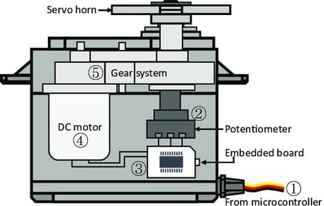
The gearbox decreases the speed of the motor, which increases the torque at the output shaft. The maximum speed of the output shaft is unremarkably around 60 RPM.
Servo control
Servo motors are controlled past sending a PWM (pulse-width modulation) signal to the signal line of the servo. The width of the pulses determines the position of the output shaft. When you send the servo a signal with a pulse width of 1.five milliseconds (ms), the servo will move to the neutral position (90 degrees). The min (0 degrees) and max (180 degrees) position typically correspond to a pulse width of i ms and 2 ms respectively. Annotation this tin vary slightly between different types and brands of servo motors (e.g. 0.5 and 2.v ms). Many servos only rotate through most 170 degrees (or even merely 90) just the middle position is near always at 1.5 ms.
For adjusting the min and max position in the code, see the section below.
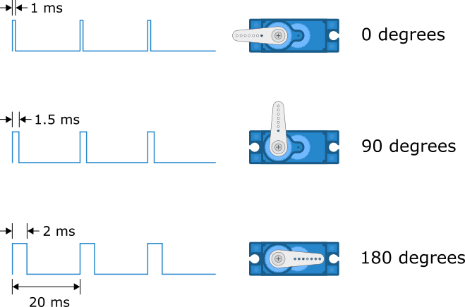
Servo motors by and large expect a pulse every 20 milliseconds or fifty Hz but many RC servos work fine in a range of forty to 200 Hz.
360-degree (continuous) vs 180-degree (standard) servo
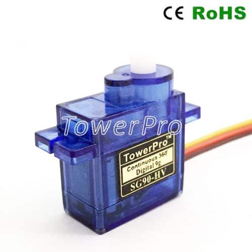
Virtually RC servos are from the 180-degree multifariousness, which ways that they can only rotate in a range of 0 to 180 degrees. Notwithstanding, continuous rotation, as well known as 360-degree servo motors, are also available.
Continuous rotation servos react differently to the command signal than standard 180-caste servos. With a continuous rotation servo, you can not control the exact position of the output shaft, only the speed and the direction. A one ms pulse will set the speed of the servo motor to total speed in one direction and a 2 ms pulse to full speed in the other. A value well-nigh 1.5 ms lets the motor stop.
If your servo behaves in an unexpected way, you might exist using a continuous servo instead of a standard i.
How to connect a servo motor to the Arduino?
Wiring a servo motor is very piece of cake because you only need to connect three wires: power, basis, and signal. The power wire is typically cherry-red and needs to be connected to 5 V.
A micro servo like the SG90 consumes around x mA when it'south idle and 100 – 250 mA when rotating, so you lot tin can ability it directly with the five V output of the Arduino. Nonetheless, you demand to be careful when using multiple or larger servo motors. If your motor(south) eat more than 300 mA you should employ an external power supply to avoid damaging the Arduino! Come across the schematic below for using external power supplies.
The ground wire is typically black or brown and should exist connected to the ground pivot of the Arduino. When using a split power supply, connect the ground wire to both the Arduino and the power supply ground.
The betoken wire is typically yellowish, orange, or white tin can be connected to whatever of the digital pins of the Arduino. In this case, I connected it to digital pin 9.
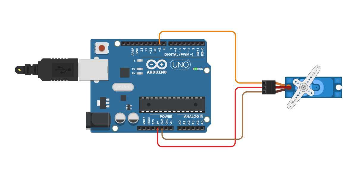
The connections are also given in the table beneath.
Servo motor connections
| Servo motor | Arduino |
|---|---|
| Power (cerise) | 5 V |
| Ground (black or brown) | GND |
| Point (yellow, orange or white) | Pin 9 |
As I mentioned before, if you are using large or multiple servo motors yous should utilize an external power supply. Merely connect the ability supply equally shown in the wiring diagram beneath. Make sure to connect the GND pin of the Arduino and the power supply together.
You can as well use this setup if your servo motor requires a dissimilar voltage than the Arduino can provide e.one thousand. 6 V or higher.
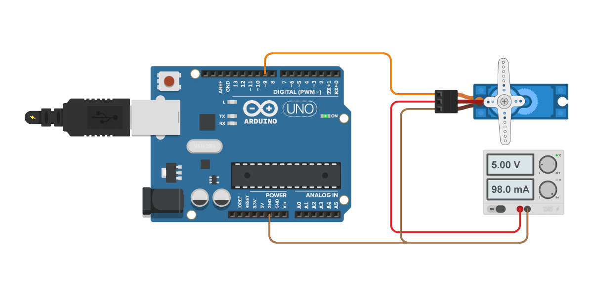
Servo motor with external power supply connections
| Servo motor | Connexion |
|---|---|
| Power (scarlet) | v V power supply |
| Basis (blackness or brown) | Power supply ground and Arduino GND |
| Signal (yellow, orangish or white) | Pin 9 Arduino |
Servo motor with Arduino example code
To control the servo motor we will be using the Servo.h library which comes pre-installed with the Arduino IDE. With the instance code below, you can command the exact position of the servo motor and it also includes code to sweep the servo arm back and forth automatically.
You tin can upload the example code to your Arduino via the Arduino IDE. Next, I will explain how the code works.
You can copy the code by clicking on the button in the top right corner of the lawmaking field.
/* Servo motor with Arduino case lawmaking. Position and sweep. More info: https://world wide web.makerguides.com/ */ // Include the servo library: #include <Servo.h> // Create a new servo object: Servo myservo; // Define the servo pin: #define servoPin 9 // Create a variable to store the servo position: int angle = 0; void setup() { // Adhere the Servo variable to a pin: myservo.adhere(servoPin); } void loop() { // Tell the servo to go to a detail angle: myservo.write(90); filibuster(thousand); myservo.write(180); delay(1000); myservo.write(0); filibuster(1000); // Sweep from 0 to 180 degrees: for (angle = 0; angle <= 180; angle += ane) { myservo.write(angle); delay(15); } // And back from 180 to 0 degrees: for (bending = 180; angle >= 0; angle -= i) { myservo.write(bending); delay(30); } filibuster(chiliad); } How the lawmaking works
The kickoff step is to include the required Arduino library. Y'all can also find this library nether Sketch > Include Library > Servo.
// Include the servo library: #include <Servo.h>
Next, you demand to create a new object of the Servo form. In this instance, I chosen the servo 'myservo' but you tin use other names equally well. Note that you will likewise have to alter the name of the servo in the rest of the code.
// Create a new servo object: Servo myservo;
After that, I defined to which Arduino pin the servo motor is connected.
// Ascertain the servo pin: #define servoPin 9
The statement#define is used to give a name to a constant value. The compiler will replace any references to this constant with the defined value when the program is compiled. Then everywhere you mentionservoPin, the compiler will replace it with the value 9 when the program is compiled.
The variable angle is used to store the electric current position of the servo in degrees.
// Create a variable to shop the servo position: int bending = 0;
In the setup section of the code, we link the servo object that we created to the pin that will control the servo. The attach() part likewise has two optional parameters, which I discuss in the section beneath.
void setup() { // Attach the Servo variable to a pin: myservo.attach(servoPin); } Control angle/position:
In the commencement function of the loop, we but tell the servo motor to motility to a item angle with the function write(). Notation that you demand a delay betwixt the commands to requite the servo motor some time to move to the set position.
// Tell the servo to go to a particular angle: myservo.write(90); delay(thousand); myservo.write(180); delay(1000); myservo.write(0); delay(1000);
Control speed:
In the concluding part of the code, I used ii for loops to sweep the servo motor back and along. This piece of code tin can too be useful if you want to command the speed of the servo motor. Past changing the delay value at the cease of the for loop, yous can adjust the speed of the servo arm.
// Sweep from 0 to 180 degrees: for (angle = 0; angle <= 180; angle += 1) { myservo.write(angle); delay(15); } // And dorsum from 180 to 0 degrees: for (bending = 180; bending >= 0; angle -= i) { myservo.write(angle); delay(thirty); } Why doesn't my servo turn a full 0 – 180 degrees?
As I discussed in the introduction, the bending of the output shaft of the servo motor is determined by the width of the electrical pulse that is applied to the command wire. Generally, a pulse width of about one ms (millisecond) corresponds to the minimum position, 2 ms to the maximum position, and 1.5 ms to ninety° (neutral position). However, this can vary slightly between brands and even different servos of the same brand. This means that you will have to adjust the minimum and maximum values in the code to lucifer the servo that you are using.
The Arduino Servo library makes it very piece of cake to tune the min and max angle of the servo motor past specifying two optional parameters in the attach() function. In this function, the first parameter is the number of the pin that the servo is attached to. The second parameter is the pulse width, in microseconds (μs), respective to the minimum (0-degree) angle of the servo motor. The third parameter is the pulse width, in microseconds, corresponding to the maximum (180-caste) angle of the servo motor.
By default, the min and max pulse width is set up to 544 and 2400 microseconds. These values piece of work for most common servos, but sometimes you have to adjust the values slightly.
I recommend adjusting the min and max values in small increments (10-twenty microseconds) to avoid damaging the servo. If the servo arm is hitting the physical limits of the motor, increment the min value, and decrease the max value.
#define servoPin 9 int min = 480; int max = 2500; Servo myservo; void setup() { myservo.attach(servoPin, min, max); } Control a servo motor with a potentiometer and Arduino
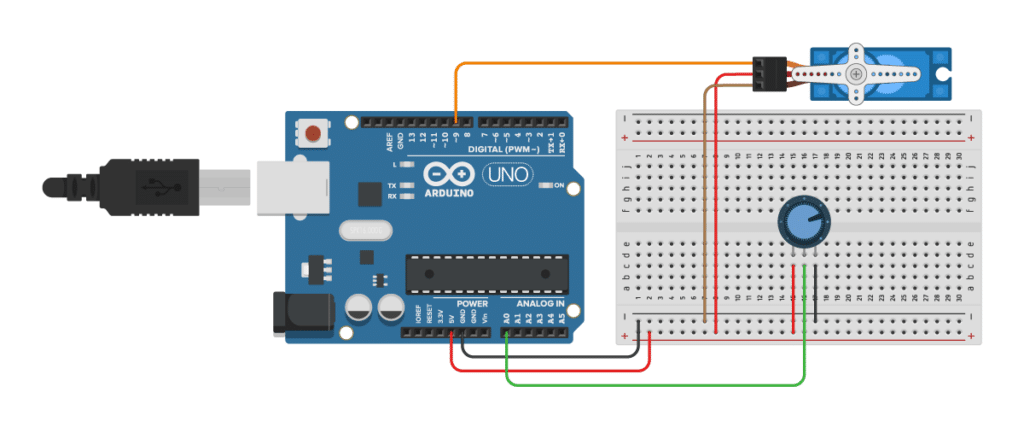
Decision-making the position of a servo motor with a potentiometer is very piece of cake and can exist very useful if yous want to adjust the motor position by hand. As you can see in the wiring diagram above, the servo motor is wired in the same way every bit before. The but difference is that I used a breadboard to distribute the power from the Arduino.
The potentiometer has three pins, connect the outside pins to 5 V and GND. The heart pivot of the potentiometer is connected to the analog pin A0 of the Arduino.
Servo motor with potentiometer Arduino example code
The example code below lets you command a servo motor with a potentiometer.
Y'all can copy the code by clicking on the push button in the acme correct corner of the lawmaking field.
/* Servo motor with potentiometer and Arduino example code. More than info: https://world wide web.makerguides.com/ */ #include <Servo.h> // include the required Arduino library #define servoPin 9 // Arduino pin for the servo #define potPin A0 // Arduino pin for the potentiometer int angle = 0; // variable to store the servo position in degrees int reading = 0; // variable to store the reading from the analog input Servo myservo; // create a new object of the servo grade void setup() { myservo.attach(servoPin); } void loop() { reading = analogRead(potPin); // read the analog input angle = map(reading, 0, 1023, 0, 180); // map the input to a value between 0 and 180 degrees myservo.write(angle); // tell the servo to go to the set up position delay(15); // wait 15 ms for the servo to reach the position } Notice that before the setup and loop section of the code a new variable reading is added and the potentiometer input pin is defined.
In the loop section of the code, nosotros read the value from the analog pin A0 with the office analogRead().
reading = analogRead(potPin); // read the analog input
Arduino boards contain a 10-bit analog to digital converter (ADC), and then this gives us a value between 0 and 1023 depending on the position of the potentiometer.
Because the servo motor can just rotate betwixt 0 and 180 degrees, we need to scale the values down with the map() role. This function re-maps a number from 1 range to some other.
angle = map(reading, 0, 1023, 0, 180); // map the input to a value betwixt 0 and 180 degrees
Lastly, we write the angle to the servo motor:
myservo.write(angle); // tell the servo to go to the set position delay(15); // expect 15 ms for the servo to attain the position
Decision-making multiple servo motors
Controlling multiple servos is merely as easy as decision-making only one just I often get questions well-nigh how to modify the lawmaking. Therefore, I accept added a unproblematic case below.
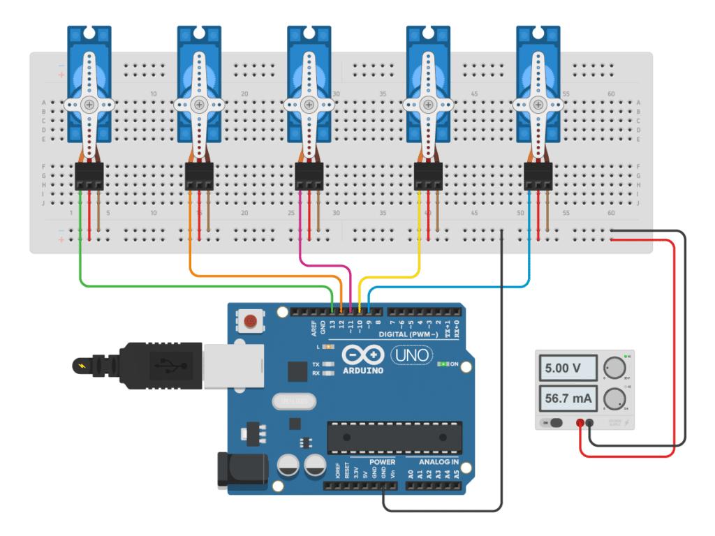
Note that y'all will have to use an external ability supply to power the servos because the Arduino can not provide enough current to power all of the motors.
For this example, we just utilise more than Arduino pins for the additional servos. All the same, this means that y'all are limited to 12 servos when using an Arduino Uno, and y'all might not have enough pins left over for other components.
Another choice is to utilize one or multiple PCA9685 PWM/servo drivers. This commuter allows yous to control 16 servos with just ii pins from the Arduino by using I2C. Adafruit also sells these in the form of an Arduino shield.

Because the setup of these servo drivers is a chip more difficult, I will cover this in a divide tutorial.
Arduino with multiple servos case lawmaking
As you can see in the case below, you just have to create more objects of the Servo class with dissimilar names. You lot tin address each servo by using the correct proper noun in the setup and loop section of the lawmaking.
/* Arduino with multiple servos example code. More info: https://world wide web.makerguides.com/ */ #include <Servo.h> Servo servo1; Servo servo2; Servo servo3; Servo servo4; Servo servo5; void setup() { servo1.attach(9); servo2.attach(x); servo3.adhere(11); servo4.attach(12); servo5.adhere(13); } void loop() { servo1.write(0); servo2.write(0); servo3.write(0); servo4.write(0); servo5.write(0); delay(2000); servo1.write(90); servo2.write(ninety); servo3.write(90); servo4.write(ninety); servo5.write(90); delay(1000); servo1.write(180); servo2.write(180); servo3.write(180); servo4.write(180); servo5.write(180); delay(thousand); } Servo motor specifications
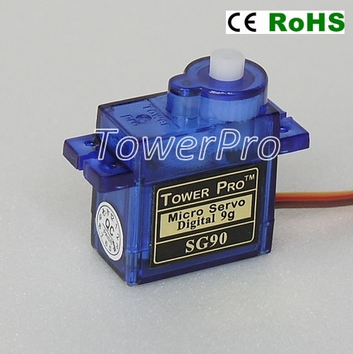
Beneath yous can find the specifications of some of the most popular servo motors on the market. The original manufacturer of these servo motors is Tower Pro Pte Ltd. simply similar models can be purchased from many other suppliers every bit well.
SG90 analog micro servo
Pinout
| Brown | GND |
| Red | VCC |
| Yellow | Indicate (PWM) |
Specifications
| Operating voltage | 4.viii V |
| Weight | nine one thousand |
| Stall torque | 1.8 kg/cm (4.eight V) |
| Gear type | POM gear set |
| Operating speed | 0.12 sec/60° (four.eight 5) |
| Operating temperature | 0 – 55 °C |
| Cost | Check cost |
Dimensions
| A | 34.5 mm |
| B | 22.8 mm |
| C | 26.7 mm |
| D | 12.6 mm |
| E | 32.v mm |
| F | xvi mm |
MG90S digital micro servo
Pinout
| Brown | GND |
| Red | VCC |
| Yellowish | Signal (PWM) |
Specifications
| Operating voltage | 4.8 5 |
| Weight | 13.four g |
| Stall torque | 1.viii kg/cm (4.8 V), 2.two kg/cm (half dozen.6 V) |
| Gear type | 6061-T6 aluminum |
| Operating speed | 0.10 sec/60° (four.eight 5), 0.08 sec/sixty° (6.0 V) |
| Operating temperature | 0 – 55 °C |
| Cost | Bank check price |
Dimensions
| A | 32.5 mm |
| B | 22.8 mm |
| C | 28.4 mm |
| D | 12.4 mm |
| E | 32.1 mm |
| F | eighteen.five mm |
MG996R high torque digital servo
Pinout
| Brownish | GND |
| Cherry | VCC |
| Yellowish | Signal (PWM) |
Specifications
| Operating voltage | 4.8 – 6.half dozen V |
| Current draw at idle | ten mA |
| No-load operating current draw | 170 mA |
| Stall current draw | 1400 mA |
| Weight | 55 g |
| Stall torque | ix.4 kg/cm (4.8 5), xi kg/cm (six.0 V) |
| Gear type | Metal gear |
| Operating speed | 0.19 sec/sixty° (four.viii V), 0.xv sec/60° (6.0 V) |
| Operating temperature | 0 – 55 °C |
| Cost | Check price |
Dimensions
| A | 42.7 mm |
| B | 40.nine mm |
| C | 37 mm |
| D | 20 mm |
| Due east | 54 mm |
| F | 26.8 mm |
Conclusion
In this tutorial, I have shown you how to utilize servo motors with Arduino. We looked at the basics of decision-making the position and speed of servo motors, how to control a servo motor with a potentiometer, and how to control multiple servo motors at the same time.
I hope you found this article useful and informative. If you did, please share it with a friend who also likes electronics and making things!
I would dear to know what projection you plan on building or have already built with servo motors and the Arduino. If yous have whatsoever questions, suggestions, or if you recollect that things are missing in this tutorial, delight leave a comment beneath.
Note that comments are held for moderation to prevent spam.

Source: https://www.makerguides.com/servo-arduino-tutorial/
Post a Comment for "Can You Read Back Servo Positions With Servo Shield"